The DMC-12 was designed in the late 70's, before the auto industry had settled on the modern computerized interfaces like ODB2 or CANBus. Its systems are primarily electro-mechanical, which makes it somewhat awkward to hook up to a computer. This page will document as much as I've learned in the context of monitoring the car.
Instrument Cluster
The instrument cluster consists of:
- Speedometer/odometer, mechanically driven by a cable from the front left wheel
- Tachometer, which is driven by the pulses coming from the 12V side of the engine coil
- Fuel gauge, which measures a variable resistance to ground through the fuel sensor in the gas tank
- Temperature gauge, which measures a variable resistance to ground from the thermostat in the engine coolant
- Oil pressure gauge, which measures resistance to ground from the oil sender
- High/low beam and turn signals, which are hot signals from those lighting circuits
- Alternator (battery) light which lights when the battery is higher voltage than the alternator
- Seatbelt light, which is a switch to ground
- Oil light, which is a switch to ground
- Brake light, which is a switch to ground (either via parking brake, or a failure detection in the master cylinder)
- Door light, if either door switch is grounded
- Fuel light, which is a switch at the bottom of the fuel sender
- Lambda light, which is a switch to ground that comes on every so many miles (when it is time to change the oxygen sensor)
The instrument cluster has several oddities. (Well, to be fair, some of these are standard things for old cars, but they puzzle me why anyone would design a system that way.)
First and foremost, the battery light provides power to the windings of the alternator when lit, and without that light the alternator will never energize, and results in a dead battery. (even while driving)
Next, the fuel sender and oil pressure sender are very small resistances. The oil sender varies from 0Ω to about 80Ω, and the fuel sender varies from 0Ω to about 90Ω. These are annoying from a circuit standpoint because such small resistances waste a lot of current (or at low currents, create tiny voltage drops that are hard to measure accurately in a noisy automotive environment) and are greatly affected by resistance in connectors between the sensor and the gauge. If they'd just picked resistance ranges like 0 to 1KΩ, this would be no problem.
The fuel level sensor also has an extreme amount of variation in the signal, from sloshing fuel. Incredibly enough, instead of damping the signal in the fuel sender they do it in the gauge. This means a digital version needs to perform equivalent damping/averaging.
The tachometer comes direct from the coil (negative charging side), so as the coil fires through the spark plug the charging side experiences electrical ringing of ~150V, which can damage a microcontroller if not suppressed with some electrical filtering.
And finally, the worst oddity of all is the connector they used on the back of the panel! I have searched high and low and talked to a bunch of DeLorean folks and even emailed a handful of European car parts companies, but cannot even determine the name of this connector much less where I can buy one.
Tachometer
Measuring the engine RPM is as simple as counting pulses... or so it seems at first. In a 6-cylinder engine, there are 6 sparks every 2 revolutions of the engine. However because of the 60-degree "V" of the engine the sparks are not evenly spaced. A quick solution is to measure pairs of sparks, which do come out evenly spaced.
The tach wire is connected to the negative side of the primary coil winding. So it is grounded while the coil is charging, and then rings violently to 12V when the ground is disconnected and the negative side floats up to match the positive side. The ringing exceeds 150V.
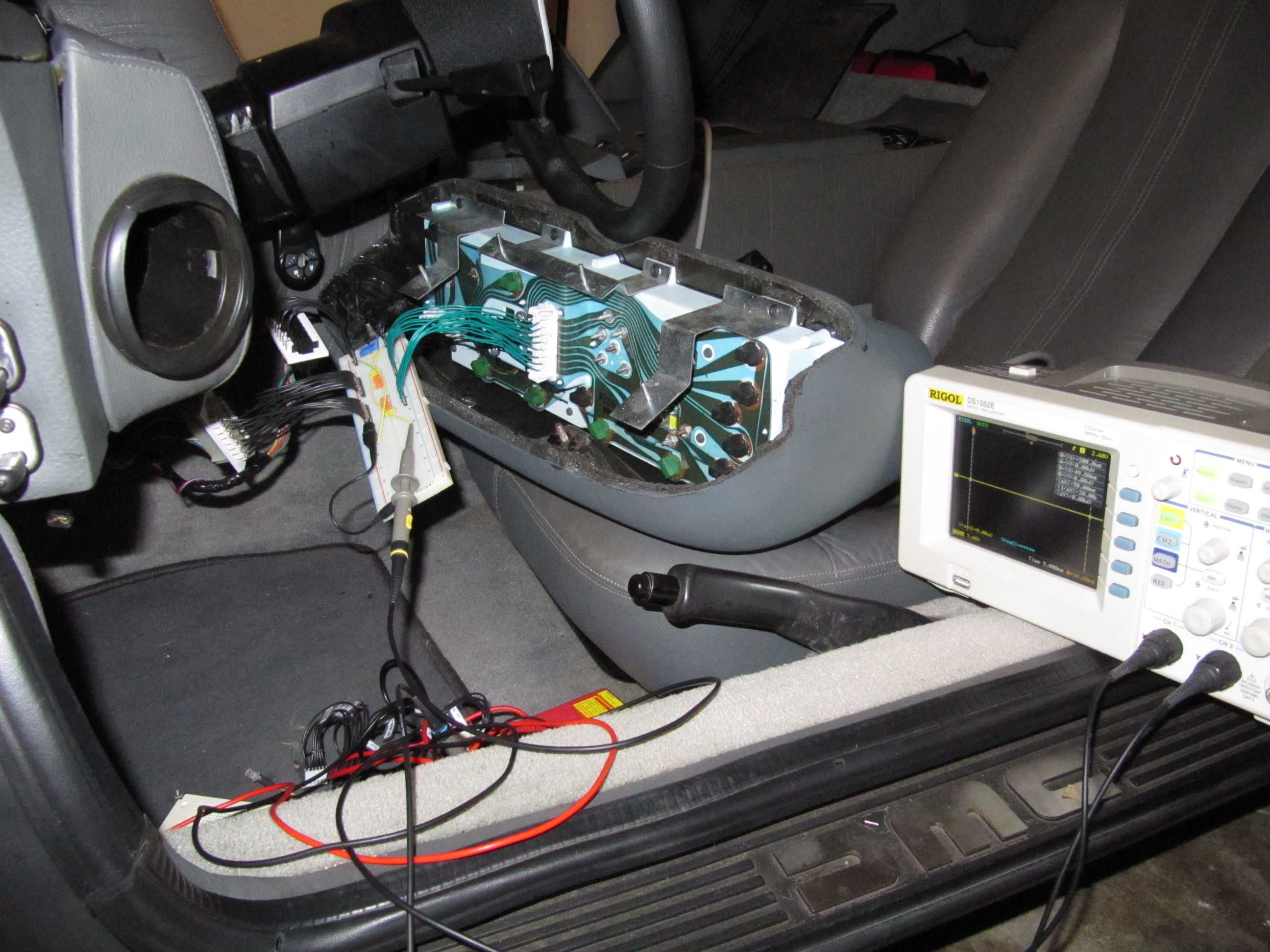
 With some experimentation and an oscilloscope, I determined that a 100KΩ resistor and a
0.02uF capacitor would eliminate most of the ringing, and then I added a diode from ground to
eliminate the negative side of the ringing. This gives a nice clean 12V square wave. Then
I added a resistor to ground to make a voltage divider which gives me a 5V square wave.
**Update** this might not be a good enough circuit,
as hard driving starts to show multiple spurrious tach pulses. To be continued...
With some experimentation and an oscilloscope, I determined that a 100KΩ resistor and a
0.02uF capacitor would eliminate most of the ringing, and then I added a diode from ground to
eliminate the negative side of the ringing. This gives a nice clean 12V square wave. Then
I added a resistor to ground to make a voltage divider which gives me a 5V square wave.
**Update** this might not be a good enough circuit,
as hard driving starts to show multiple spurrious tach pulses. To be continued...
With a 5V square wave, I just connect it to an interrupt pin on the microcontroller, and every time the interrupt fires I record the current clock time. Some quick math tells us that the lowest frequency (at 500 RPM) is 25 pulses per second, and the highest (at 6500 RPM) is 325 pulses per second. So, there will be at least multiple milliseconds between pulses which makes this easy to read with a 16Mhz microcontroller. I keep a history of the timestamps of the last 7 pulses received, and then average the pulse-pair intervals (again, because pulses are not evenly spaced, but pairs are) to get the current RPM.
Fuel Level
Fuel Gauge
The DeLorean uses a classic fuel gauge design where current passing through the gauge heats a metal strip that bends, causing the needle to move. The circuit grounds through a variable resistor attached to a float in the tank, and the lower the resistance, the higher the current and the lower the gauge reads. This also means that a bad ground connection or loose wire makes the gauge read high, which is kind of a bad default mode of failure.
The heated metal strip design is supposed to act as a damper to hide the sloshing of fuel in the tank. As it happens though, the DeLorean fuel tank has only one baffle around the fuel pump, and the rest of the fuel sloshes wildly while driving, more than even the damping in the gauge can hide.
The fuel float is a variable resistor from 0Ω to 90Ω (though my gauge reads Full at 80Ω), connected to ground. When powered by 13.5V and the sender is near 0Ω, the stock gauge drops about 200mA through it. This seems a bit excessive to me.
Unfortunately, there's not really a good way to measure this without changing the circuit. Because the fuel gauge connects directly to ground, and can drop to 0Ω, most of the resistance needs to be on the source side, which means the signal voltage is a very small value. Using the normal 13.5V car voltage to power it would waste a lot of current, and if it got disconnected the voltage on the microcontroller would float up and burn things out.
In my first iteration of the design, I decided to power it from the 5V microcontroller power with a 560Ω resistor, so the voltage varies between 0 - 0.69V which is 7 bits of precision on the 10-bit microcontroller ADC. (and conveniently fit in one byte) However the small resistance I was measuring could be significantly affected by resistance in the connector, and I was reading a tiny voltage against a backdrop of all the electrical noise in the whole car, so I never got a very reliable reading from it.
After my fuel pump started making a lot of noise, I upgraded to the DMC-Houston combined pump-and-sender unit. This worked great on the stock gauge, but not with my circuit. After some emails with DMCH, I learned that their unit was using pulse-width modulation to simulate the resistance-to-ground, so I would need to add a capacitor to get any steady reading, or try to measure the PWM. Meanwhile, the DMCH sender has its own float, so the original float was now disconnected... I made an adapter for the connector, and ran it direct to the microcontroller, so now I have a clean isolated circuit, and I can get reliable readings from it. I still wish it were a potentiometer.
I still intend to make a circuit that is compatible with the DMCH unit at some point, and then I will use the average reading from the two senders.
Fuel Light
The fuel light is just a plain switch at the bottom of the fuel sender. If the float reaches the bottom it grounds the switch. I just set a pin to use a pull-up resistor and then reading the switch is trivial. ... Well so actually I also added a resistor and 5.3V Schottky diode to protect against static electricity or accidentally connecting the wire to 12V while working on the car.
Oil Pressure
Oil Gauge
The Oil Pressure gauge is really not that important or accurate of a measurement, but it gives enough feedback to the driver that you can tell if something isn't quite right with the oil pressure. This makes it useful even though there is a separate oil light circuit to warn about complete loss of oil pressure.
The oil pressure sender is a resistor of 0Ω to 80Ω or so, connected to ground. It is the same deal as the fuel gauge, so I used the same circuit design. See above.
Oil Light
The oil light is also just like the fuel light. It is a grounded switch that closes when there is no oil pressure. Same circuit here too.
Temperature
The temperature sensor measures from the engine coolant. This can be a problem if something fails and the coolant stops circulating, because then it doesn't get shown on the gauge. One of my future upgrades will be to put temperature sensors directly on the engine block, or heads.
In the meantime, I'm just using what I've got. The stock temperature sensor is a resistor that starts at several thousand Ohms and drops logatirhmicly as it heats up. Using the stock gauge as a reference, 100 °F is 1000Ω, 220 °F is 100Ω, and 260 °F is 50Ω. Since the important part of that range (overheating from 100Ω to 50Ω) is in the same range as the oil and fuel, I just used the same circuit again.
Alternator
Alternator Light
The DeLorean stock alternator is wired with this "clever" idea that when the ignition is on and the alternator isn't spinning, an incadescent lamp wired from ignition (13 volt) to the alternator windings (0 volt) will light up and deliver just enough wattage to prime the alternator. When the alternator starts generating voltage, there is no longer a voltage drop accross the light and it goes out.
There are several problems with this. First, if the light burns out the alternator won't power up. You can detect this by the absence of the battery light when you first turn on the ignition, and by the low reading on the voltage gauge. But, it isn't super obvious.
The second problem is that you can't change the light for an LED, because an LED doesn't deliver enough current. I measured that the original bulb draws 180mA, where most LEDs use 15-30mA. If you change it to an equivalent resistor, you have the difficulty of the resistor heating up. 180mA * 13.5V is 2.43 Watts! Really, the light should also heat up just as much as a resistor, but I find the resistor getting startlingly hot where the light didn't seem to, perhaps because the light was actually radiating a lot of that power as infrared light.
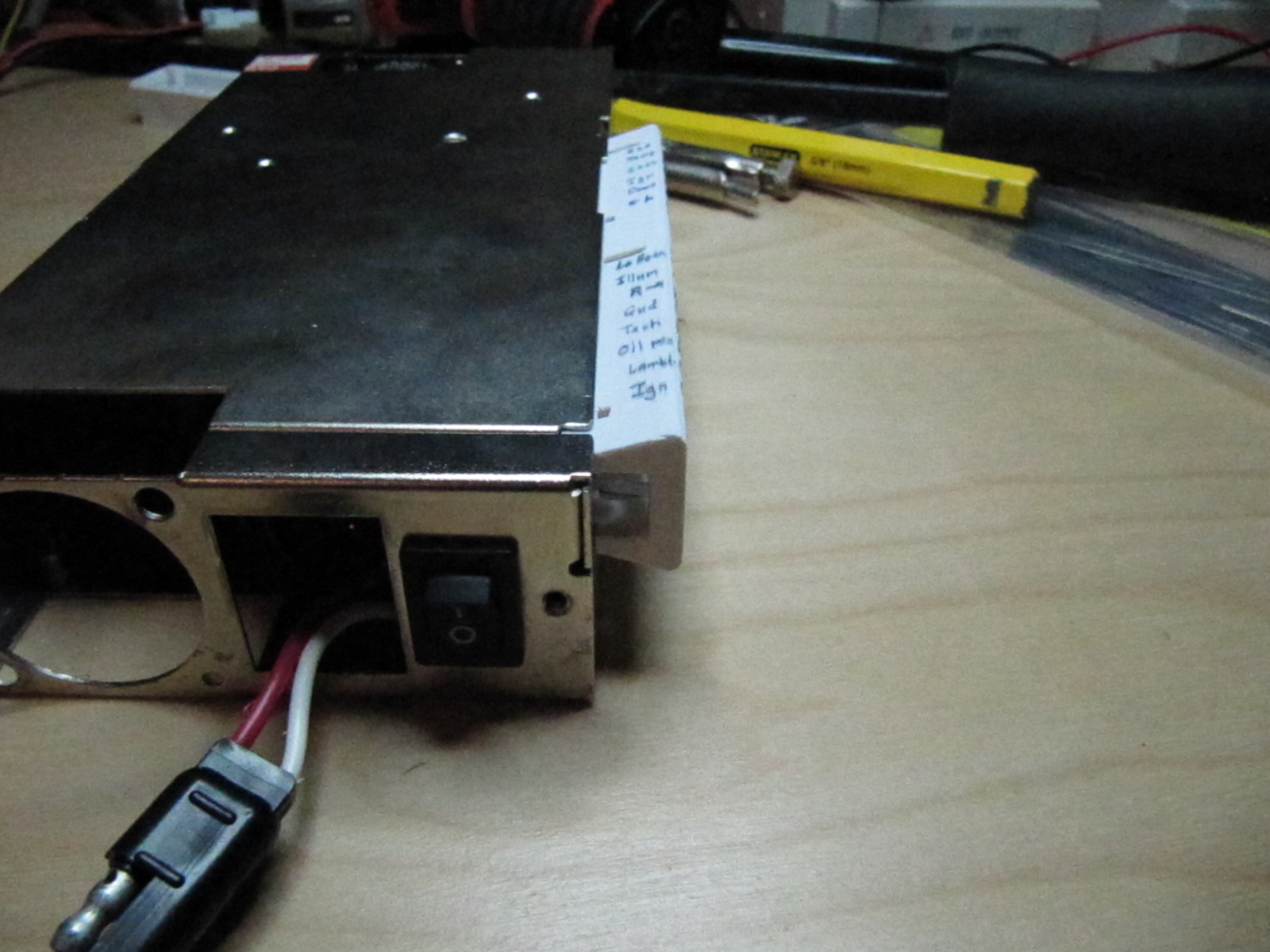
I eventually decided on a 100Ω 5 Watt resistor and mounted it right up to the side of the metal case housing my control board, so that the case can absorb some of the heat.
Funny sidenote: on one of the early designs I discovered that using too small of a resistor would pass enough current that the engine wouldn't shut off! The current through my resistor was keeping the ignition circuit powered. A diode in series with the light is probably a good idea.
Alternator Ammeter
The stock DeLorean doesn't have any way to measure the output on the alternator or the drain on the battery, which are two measurements I wanted available. I haven't completed this part of the project yet, but I added a shunt resistor (a bulky resistor with a tiny precisely calibrated resistance) on the back of the alternator, and then I can use a microcontroller to measure the voltage drop across it. Likewise, i'll be adding one to the positive battery terminal. The trick with the battery terminal one is that it dumps some 200 Amps into the starter motor when cranking the engine. But, it turns out they make shunt resistors in very large sizes, so I got one calibrated for a 0.075 V drop at 250 A, which shouldn't affect cranking.
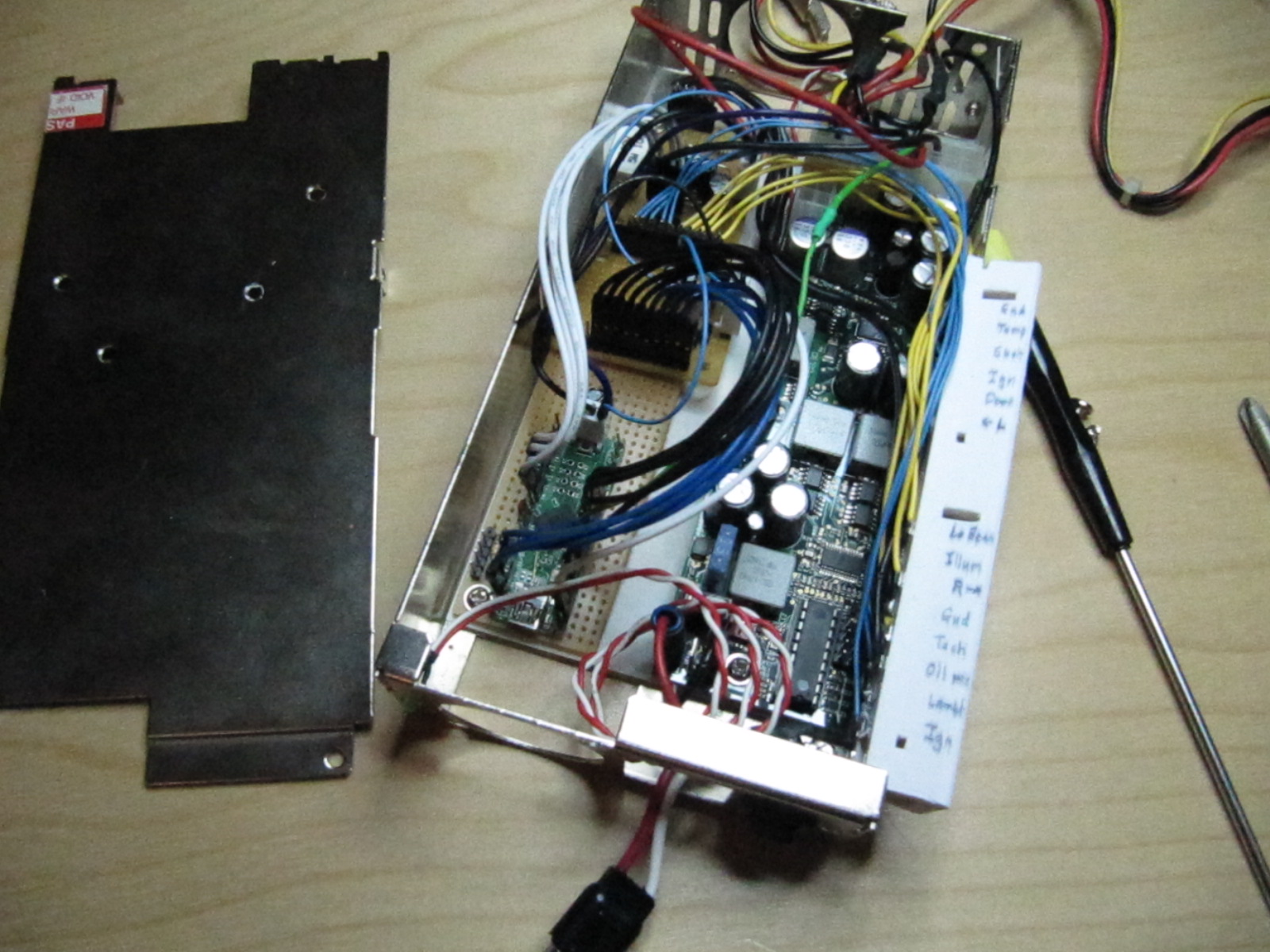
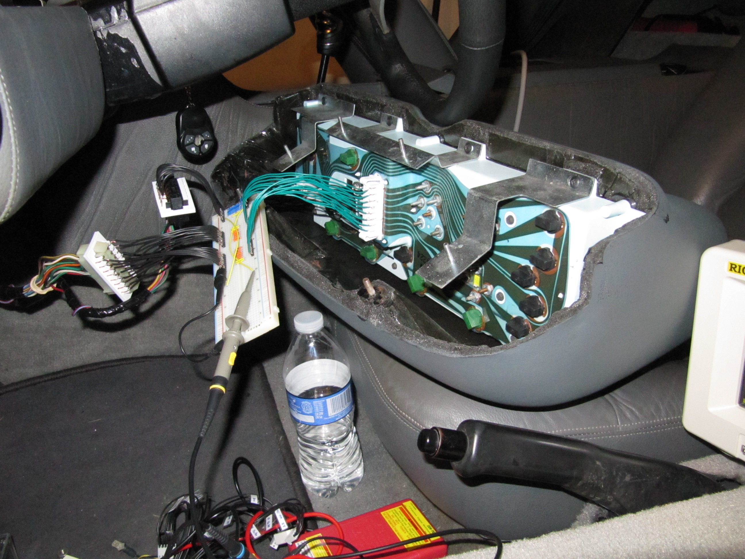
Instrument Cluster Connector
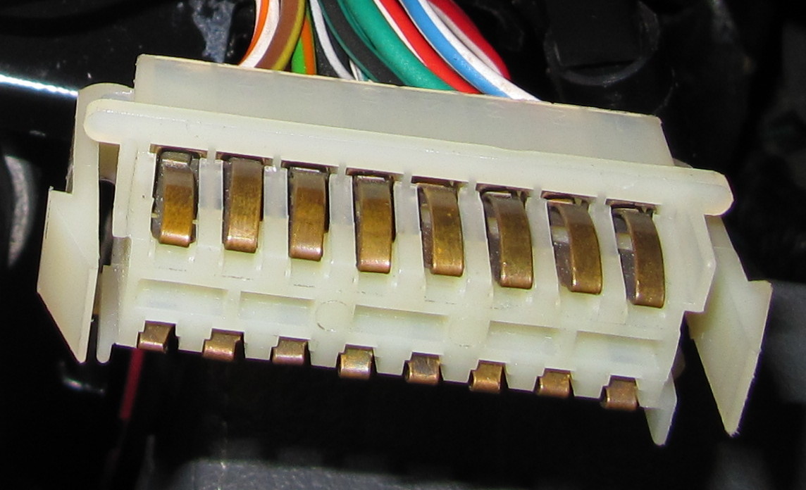
This stupid connector has cost me more time than I care to count. There are two of them, a 16-pin (above) and a 12-pin version which have the exact same dimensions other than the width of the center area. They plug into holes in the back of the instrument cluster and press those springy contacts against pads on a printed circuit. The design isn't bad, but the connectors are big and bulky and nobody sells a mating female side for them. The smart thing to do here is just splice into the wiring, or just cut it off and re-attach with some more common connector. But... I just couldn't bring myself to cut the original wiring.
In my first attempt, I wrapped them in plastic wrap and then mashed them into a ball of epoxy putty. When it hardened I drilled out little holes for each pin and stuck wires through, and then added a pad of solder on each wire to make wider contact with the spring connector. This worked for a while, but my "clip" eventually broke off (because I was flexing the epoxy to attach and detach it) and then finally the whole connector broke apart.
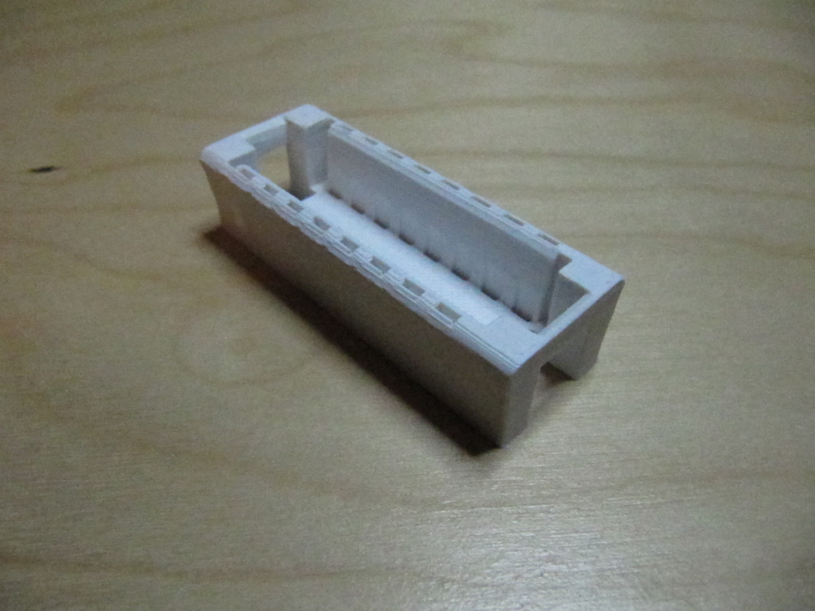
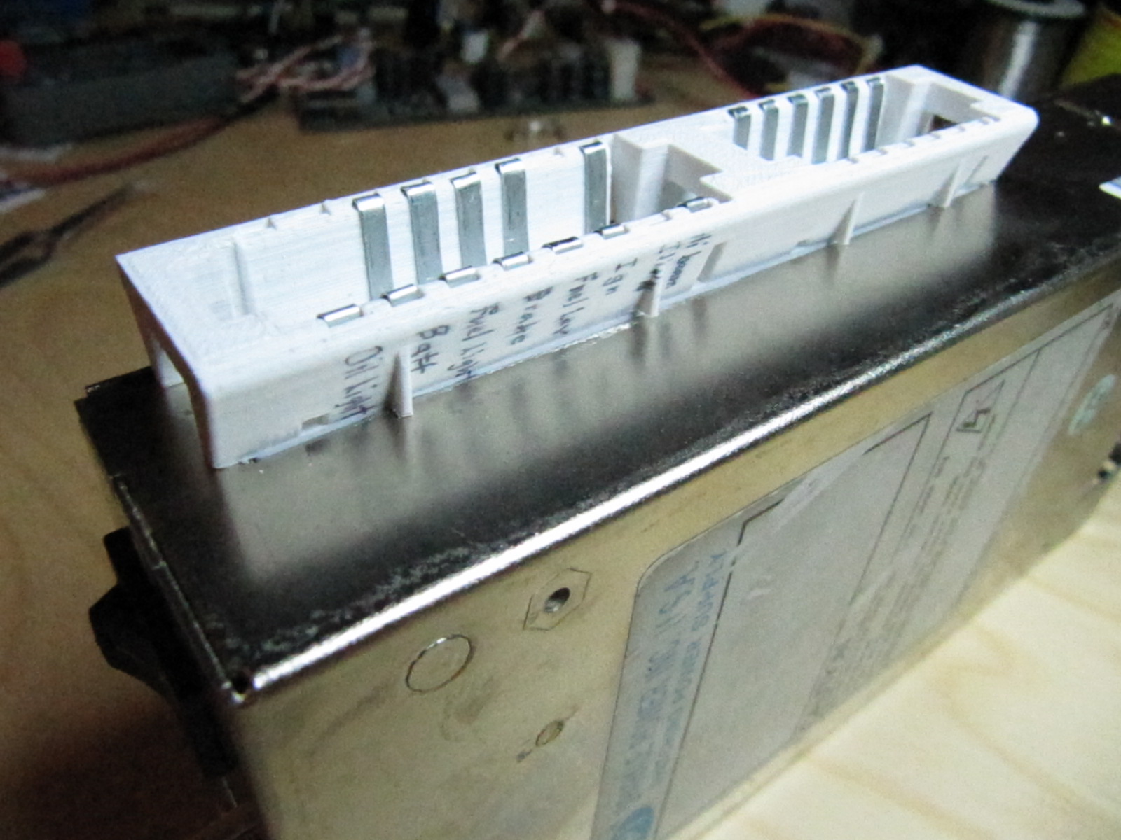
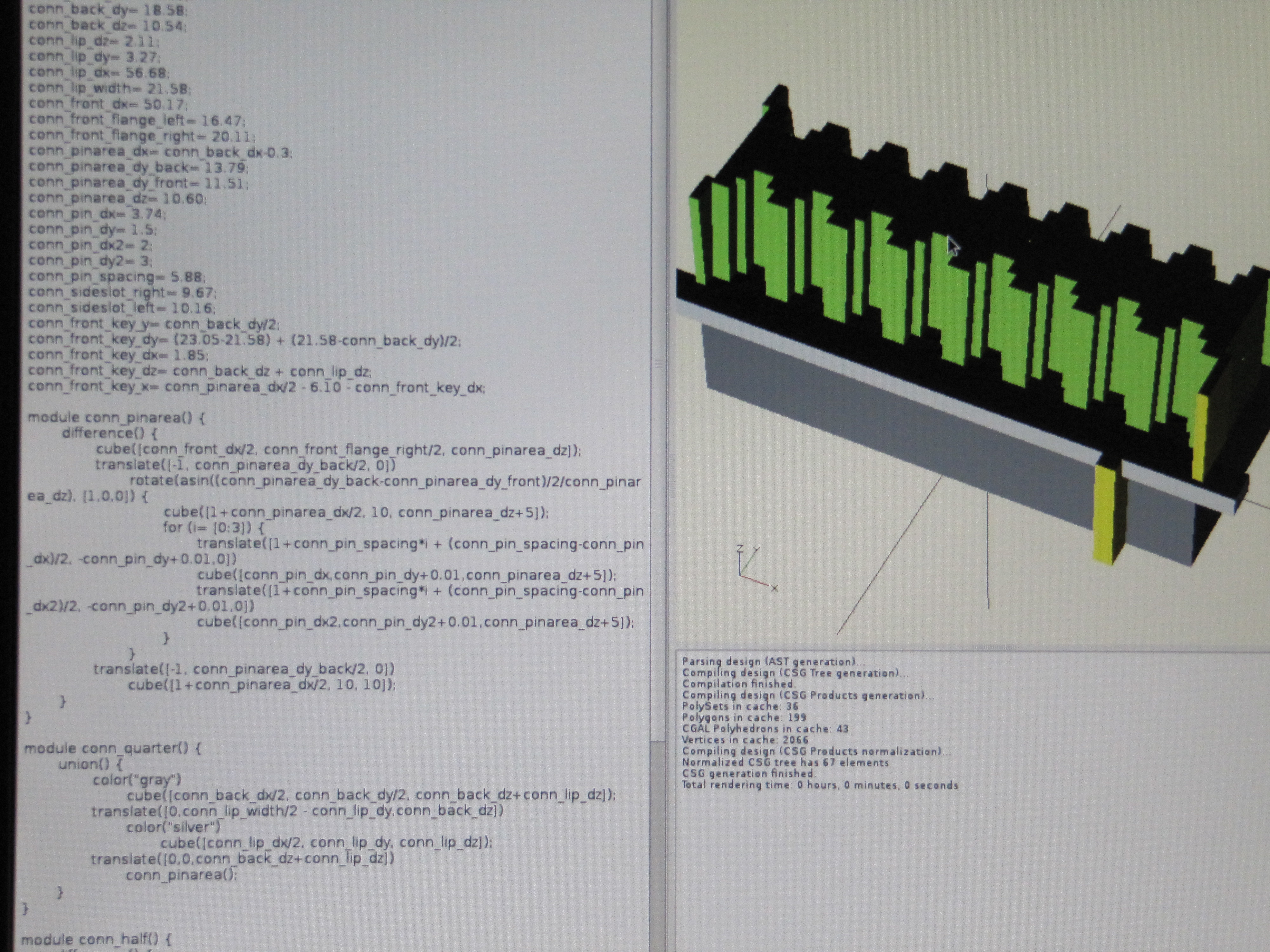
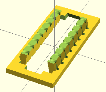
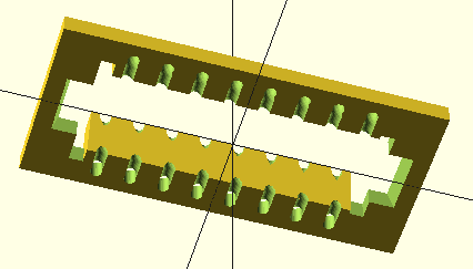
In 2012 when I bought my MakerBot, I decided to take another crack at it. I first designed the male end so I could make sure I had all the dimensions right. Surprisingly, the 3D printer nailed the dimensions to sub-millimeter precision!
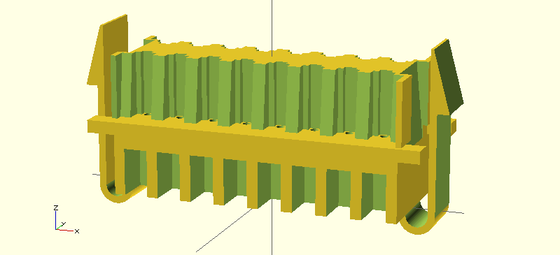
For the mating side, I came up with something pretty simple that would press wires up against the sides, much like my epoxy connector:

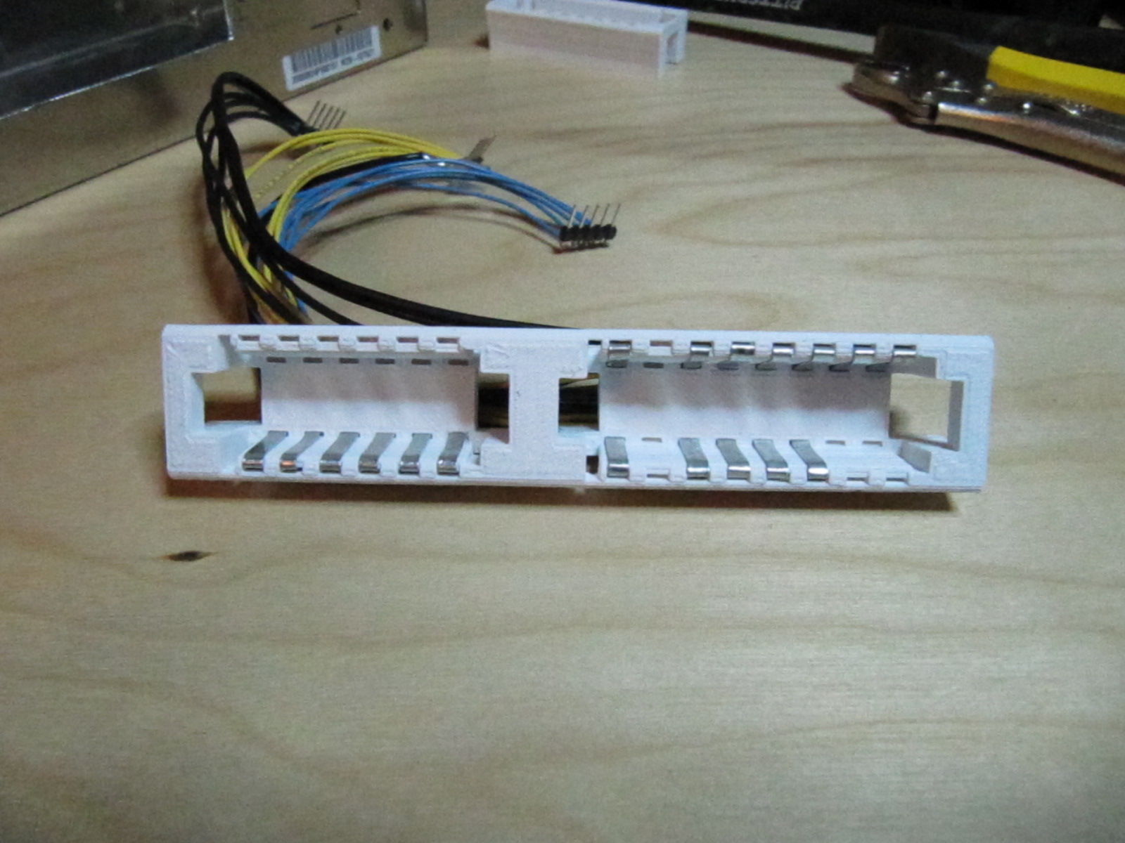
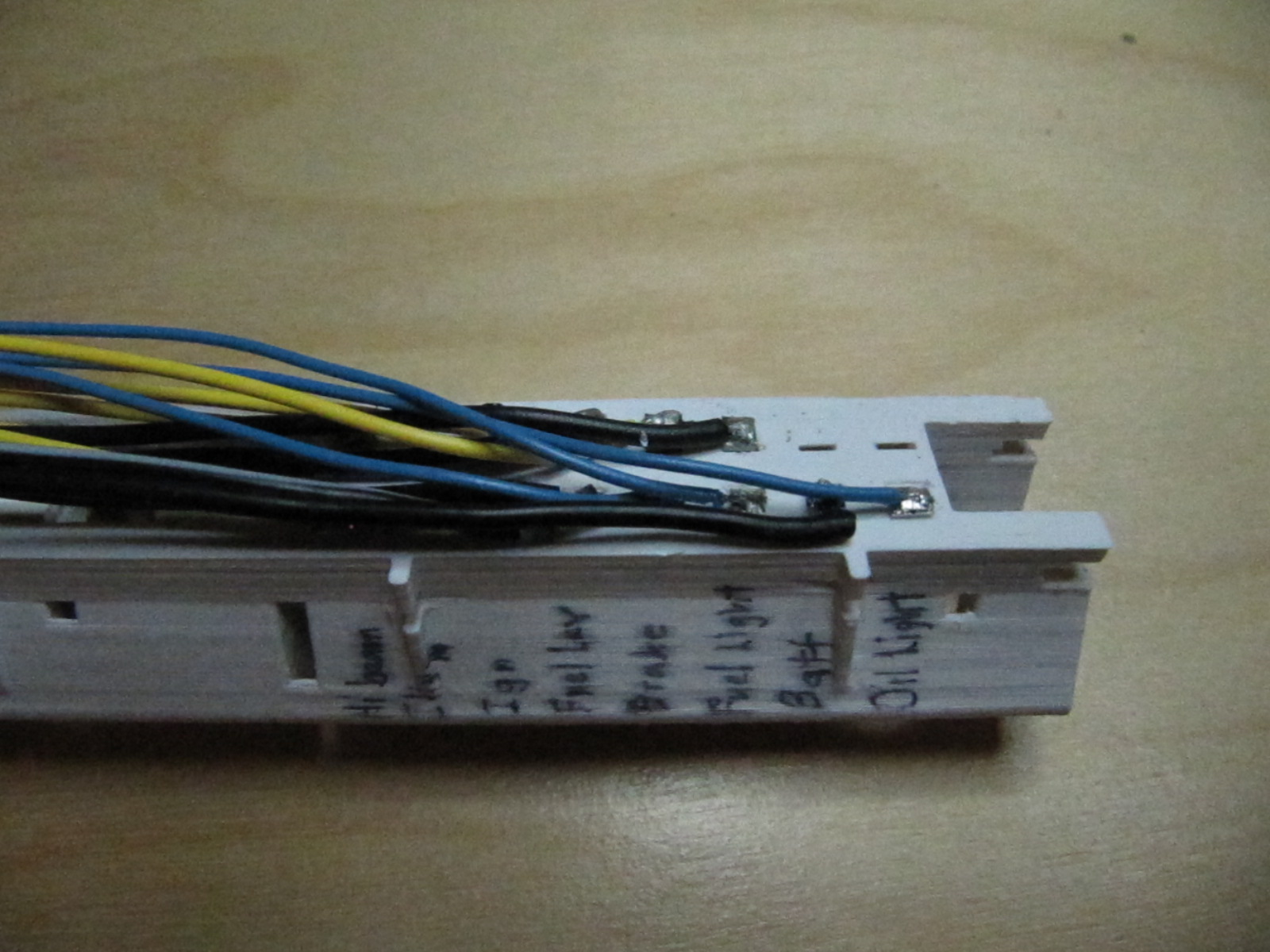
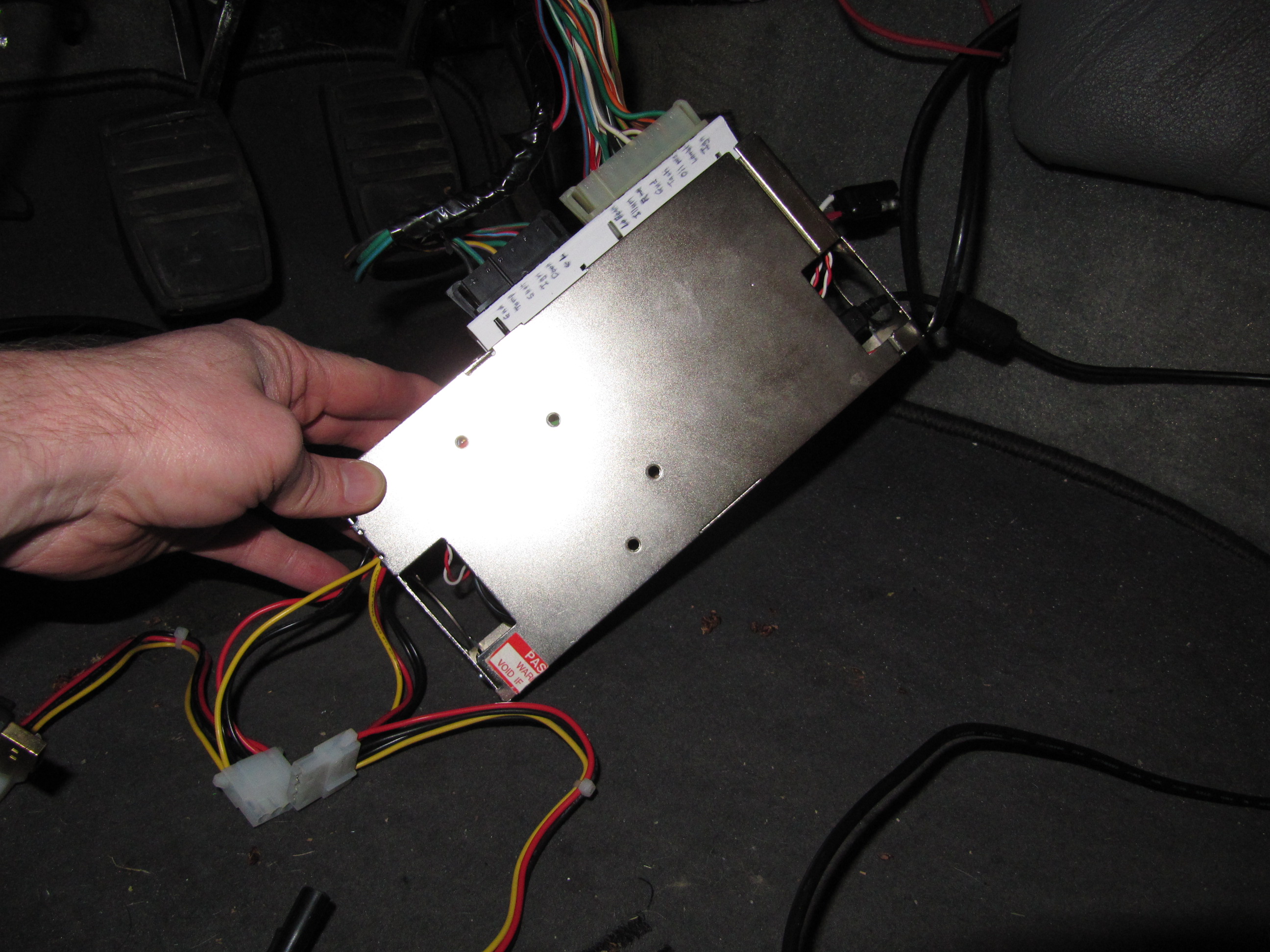
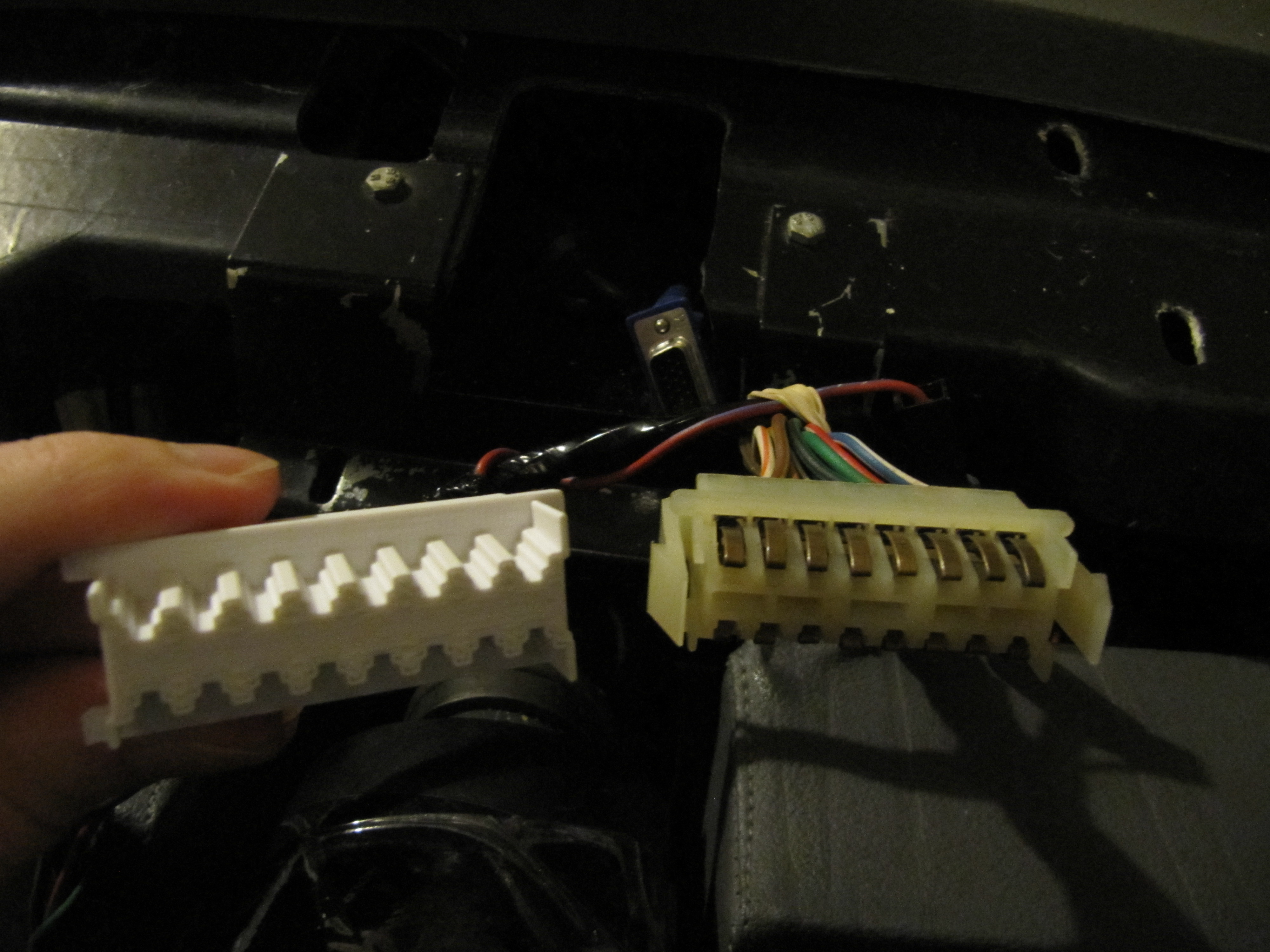
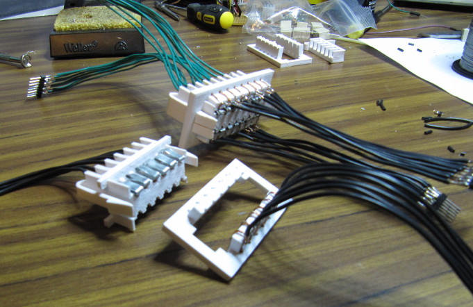
Getting contacts for the male connector turned out to be hard, as I couldn't really find the pins anywhere and I didn't have the right materials to make my own. I made some out of scrap tin I had, but they didn't have much "spring" to them, and would stop making solid contact after a few plug/unplug cycles. But, it was enough to make a mating pair and do some testing:
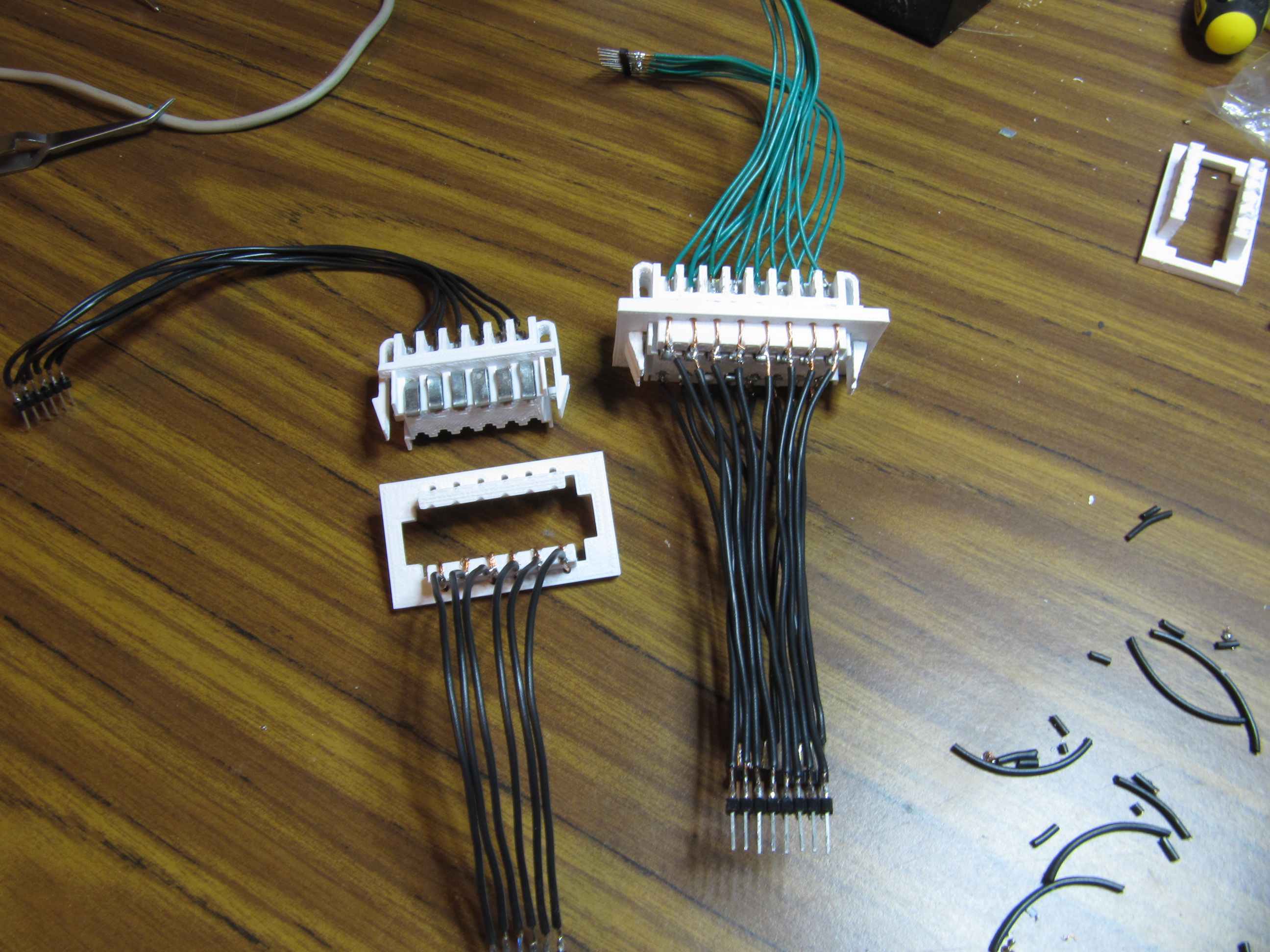
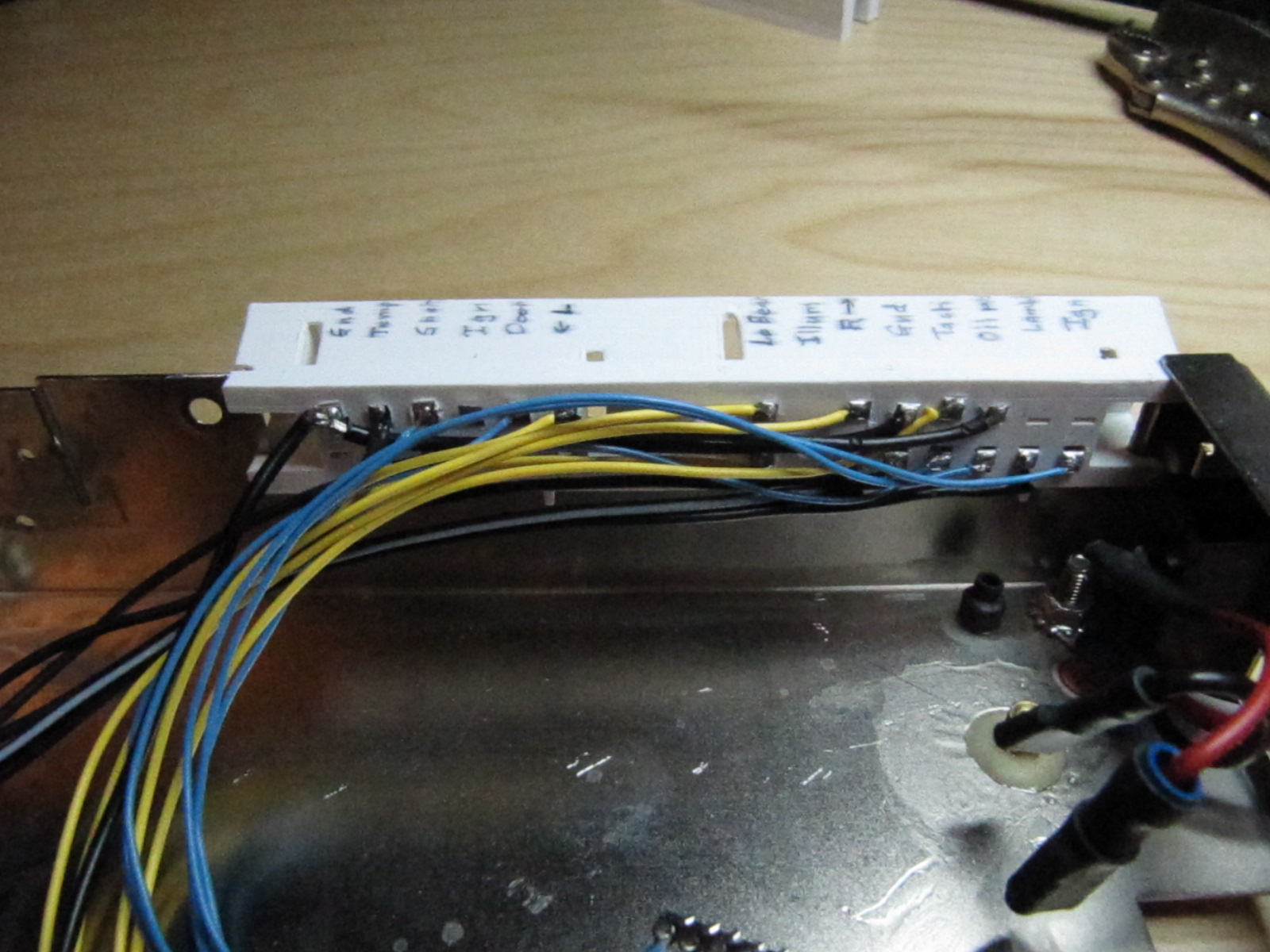
I used that for almost a year, but the contacts weren't always reliable, and I got tired of fiddling with it each time I took the microcontroller out. Also, the connector was hanging loose under the dash and there wasn't any good way to anchor it. Also the wires were a mess and I wanted to get them into a more tidy configuration. So, I began work on "version 2", which would enclose the contacts more completely, (preventing anything from shorting out) hold more tightly, and which would be small enough to mount into the wall of the metal box holding the microcontroller and power supply. I would have just let the connector plug into the face of the box, but there really wasn't enough room on the inside, so I needed to keep most of the connector on the outside while letting my wires slip in.